Project Home Link:

!YOU MUST READ THE SAFETY INFORMATION IN RED IN THE FIRST POST!
Click the 'Project Home Link' above ^ to start on the first page, and click 'next' after each article to read in order..
(You can click each photo in the articles to see fullsize)

Pages

Sunday, September 28, 2014

Been a While...

While you have been off looking at pictures of kittens, I have been doing stuff on the router build.
You can see the continuing efforts here:
https://plus.google.com/u/0/photos/106857901155881333586/albums/6063547350605671857
and
https://plus.google.com/u/0/photos/106857901155881333586/albums/6064043334578995761
It should be up and running in the next couple months.

Monday, May 30, 2011

Slippery Smooth Rails

Creating the Rails

Earlier, I had purchased the rail material, but I discovered that, unlike advertised as 3/4" x 1/8", it was actually 0.130" x 0.755" and had radiused corners. The bad part of this was even such a minute change is pretty serious in SolidWorks. If an assembly is not set up correctly, all the 'mates' will crash and you will have to go through and re-evaluate each component, especially since I have cut all the MDF parts out already. I can still adjust the method the rails are installed with, and adjust the dimensions to allow it to still work. I was going to cut grooves into the support members at 45 degrees with the table saw to accept the 'legs' of the angles, but trying to determine the measurements in real life was just too difficult. So, I changed plan and decided to use a set edge distance and use the router to carve a rectangular slot to a specified depth and of precision width to snap the angle into. It has required me to create a setup for the router so I can control it with precision. Having solved that problem, I can now go forward with the creation of the actual angles. The first process is to cut them to the required lengths: 79.5, 42.288, 15, 8, 5 inches.
I have a cool support stand for my chopsaw, so I brought it outside and set it up.
I measured very carefully each part, starting with the long ones first.
Long ones first-cut to split the line

Chopsaw set-up with 12" carbide blade

Always pre-trim the end to make sure it is true


Look close-measure 42"(from 10, burn 10), then .288"

All the rails cut-scrap is on top laying sideways

Top view of the parts-nice day

After careful measuring-microdot, centerpunch, center drill

Centerdrill-does not flex; results, then 7/32", then Letter 'I' drill

Learn to adjust your drill press speeds

7/32" intermediate holes completed

The 16-speed drill press I use

Harbor Freight 115 piece HSS drill set: Fractional, Number, Letter

The super tapper-$85 at Grizzly

Tapper counterweight transfer wheel and support bushing

Makes perfectly perpendicular holes with ease

Don't forget to use aluminum tapping fluid for nice threads

Completed 5/16"-24 threading-I hit it lightly with a chamfer to clean it up

So shiny new threads

The tap holder assembly-snaps into shaft

Preparing to install bearings


Snug the allen head bolt tight to the nut

Don't over tighten the bearings in the rails-The aluminum is soft

Completed X-axis support rails-note stagger on bearing holes

End view of rails showing clearance of rail 'points'


Taming the Wild Saw of DEATH

Holy Crap! I cannot believe they actually sell something like this..
Wild Saw of DEATH
I purchased this for about $15 at Harbor Freight a few years ago, thinking that at some point cutting dado slots would be something I would do..Well, now is the time. So I read the directions, set the thing up for 0.75" and bolted it to my arbor. You are supposed to take the two slanty cylinders and move them 'eccentrically' opposite each other, which induces a 'controlled' width wobble in the blade allowing you to cut a wide slot in your stock.

 Hmmm, first thing is that my throat plate was not going to work. Luckily I have a CNC plasma cutter, so I jumped on SW and whipped out a quick design which I cut out on the PlasmaCAM. I am quite proud of how it came out-it worked great with the WSoD.

Throat plate for WSoD compared to stock throat plate


So set at 3/4"..check.
Arbor nut tight..check
Power saw up..crap! run!!!
This thing was vibrating so wildly, the
only thing you could imagine was it
getting free and screaming across the room with carbide teeth wildly tearing through everything in its path!!

I ain't getting near that while it's running..do I dare go near the saw to turn it off? So, anyway I got brave and took a test piece and tried to cut a slot while fearing for my life and extremities. I used the miter to run a piece through. When it was all over, I inspected the slot and it was crap, and it would not even cut deep enough for the design. So I decided maybe in about another 15 years I might try it again, for say an 1/8" slot or maybe call the DoD and let them know I have something fierce they spin up and can drop out of airplanes over in Afghanistan. The WSoD went back in the package and I put the 'wide' normal carbide blade back on.


Regular non-WSoD carbide blade


Ah, peace, serenity and multiple passes

So in just a few passes, I was able to
create a precision slot of a controlled
and sufficient depth. There are not too
many of these, so I will just go with this.
There are plenty of other processes you must do as well, like drilling holes to mate the other parts.
One of the things I needed to do was to create a jig to allow me to drill the toggle holes in perfect alignment with connector bolts. This next sequence shows how I created the jig. Two 1/4" holes were drilled to hold the 'side' to the 'top' as shown below. The 18mm OD of the 10mm drill bushing (in background of top pic) was created using a forstner bit, which if I remember was pretty close to the 18mm.

Building the Toggle alignment jig:

The way this whole contraption is held together is with 'toggle bolts'. The 'toggles' are 10mm in diameter and about 5/8" long with a screwdriver slot in one end and a 1/4-20 threaded hole radially through the cylinder. So you must drill a hole partially through for the toggle, with a carefully aligned perpendicular hole to intersect at just the right spot.
Using forstner bit to make bushing hole

10mm ID 18mm OD drill bushing in background

Drilling 'top' of drill jig for toggle bolts

Toggle holes completed


Z-axis top plate toggles drilled


Ready for slot to be cut
This series shows the steps including toggle hole drilling, toggle bolt holes drilled and assembly.

Assembly of Z-top plate to vertical member

Toggle close-up and slot tolerance

Z-motor plate assembled to vertical member

Carriage awaiting the Z-rail plate (under hammer-yet to be drilled)

Z-rail plate getting holes drilled (has yet to have edges beveled)
Z-rail plate installed

Rear view of carriage

Bottom of carriage showing precision fit of components

Back support of carriage and drive-screw hole

Side view of nearly completed carriage assembly

Even though the carriage looks completed, I must yet bevel the edges to accept the Z-axis long rails on which the router will ride. Another item is the lower Z-axis drive screw support which will need to be attached the lower front of the rail plate.


Side view of the router support grips

Caught in a Dust Storm

Each piece of MDF is ridiculously heavy. But it cuts glassy smooth. I used a Red Devil 7" narrow kerf carbide blade, which cuts with excellence. Having created my cut list for all the MDF components, I took my table saw to the hangar for some precision cutting. No sawdust here. Only microfine dust which is electrostatically charged and migrates everywhere. Kind of a preview of coming attractions for what a colossal mess you will be able to make with the router when you CNC MDF. One cool thing with SolidWorks is it is really easy to take an assembly apart. The following photo shows all the parts.
The way I draw, I create the basic stock component size, so I can look at the part, roll it back to the 1st step and know how big a piece of material will be required. I can also create an assembly to nest these parts for efficiency.
In this case I did not nest, but I cut the largest parts out first in order of descending size. The table was the largest and had quite a bit of leftover which I made some of the smaller parts from. I purchases the table piece last year and created it outdoors (earlier photos). So I loaded up the table saw and brought it to the hangar. The floor is very flat, it is heated and it was very cold outside here in Montana at that time. The table saw is a Ryobi BT-3000 Cutting System. I went hog wild purchasing every accessory sold for the table at the time (15 years ago).
Table saw set-up
The saw is quite lightweight (nice), disassembles for transport and has the folding exit table extension, fence extension, side table extension kit, wheel kit, accessory table kit, miter arm kit, and am/fm/cd/8-track :-) And I have a couple of Harbor Freight roller stands to help also. I tried to only work from the front, as I could see the dust was accumulating very quickly and deeply at the rear as the parts stacked up. One of the kids was going to 'help' me clean up and I am glad I headed him off at the pass. I was able to very controlledly sweep the mess up without creating a dust storm (more) and used the vacuum to get the remainder up. But next time this will need to be done outdoors. The dust was confined to only the nearest six feet, and the aircraft parts within this range were able to be cleaned up with only a damp rag.. But if there was a breeze of any kind, there would have been a nightmare of dust coating EVERYTHING. So a dust handling system will be a must have, and I have already begun building from a quality planset I got from eBay. I cut the parts with a tolerance of about the width of a tape measure mark (a few thousandths), but certainly less than 1/32 of an inch.
Some typical parts sized to match
View of match part across the top

View of matched parts down ends-good tolerance for a table saw

Keep in mind that this is only the basic outside dimensions of each part, which most will require further post-processing of hole drilling and profiles creating.
To give you an idea of mess I was creating, see this photo:
High view of set-up and mess


Closer view of dust output

Amazing how the floor disappears
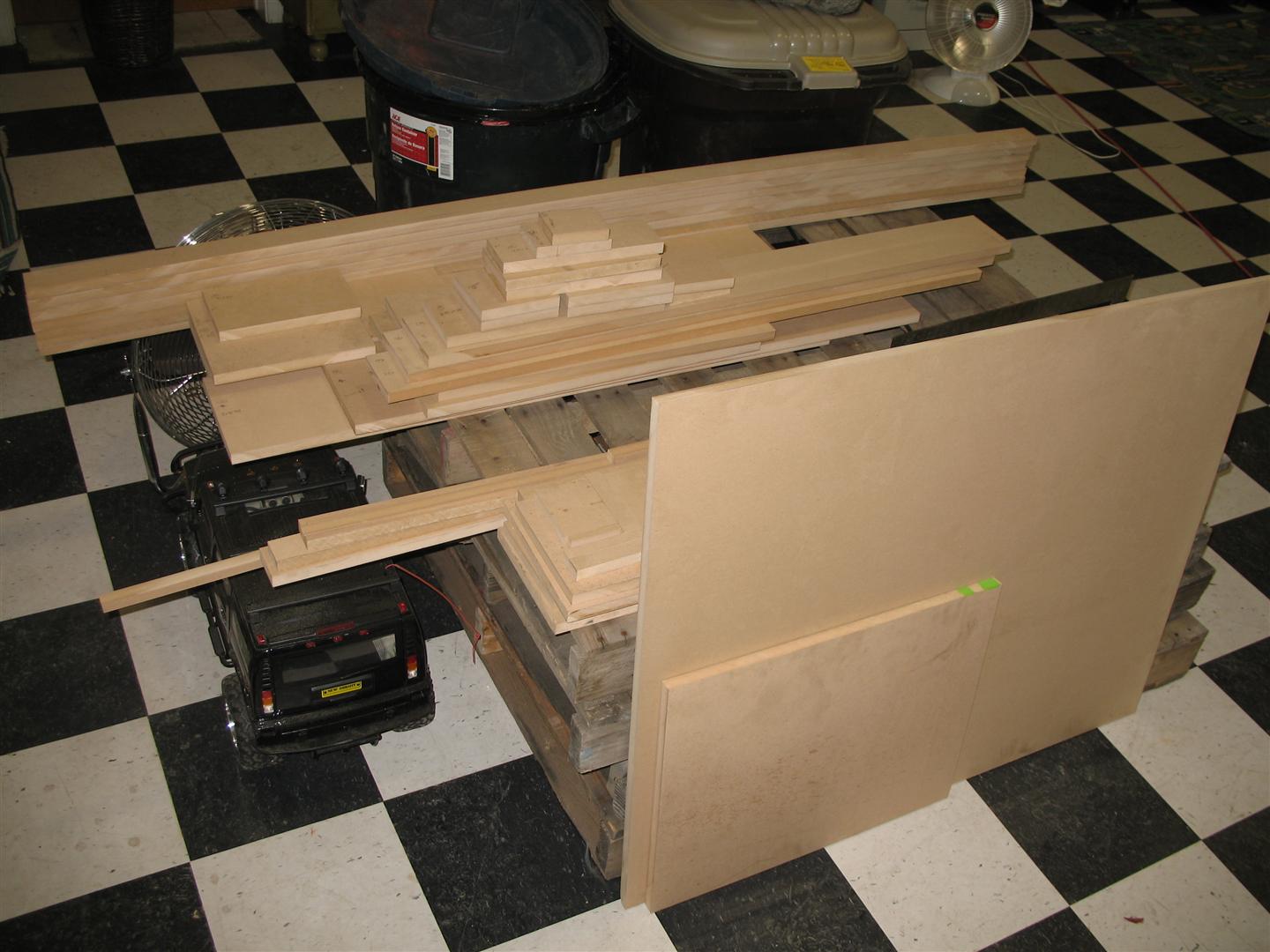
But, I got all the parts cut, so I carefully transported them and the saw home again. Here is a view of the finished pile:
Finished pile (near)
All the table base support parts, gantry parts, carriage parts and Z-axis router support parts are here.
'Scrap' on left< >Parts on right

Near pile and big piece is 'scrap' (for other projects)

Scrap pile

The Parts-now all will need more work
Notice all the parts are labelled-each looks like the next, so in case of an avalanche, I will be able to sort it all out. Load 'em up, Move 'em out!