Holy Crap! I cannot believe they actually sell something like this..
 |
| Wild Saw of DEATH |
I purchased this for about $15 at Harbor Freight a few years ago, thinking that at some point cutting dado slots would be something I would do..Well, now is the time. So I read the directions, set the thing up for 0.75" and bolted it to my arbor. You are supposed to take the two slanty cylinders and move them 'eccentrically' opposite each other, which induces a 'controlled' width wobble in the blade allowing you to cut a wide slot in your stock.
Hmmm, first thing is that my throat plate was not going to work. Luckily I have a CNC plasma cutter, so I jumped on SW and whipped out a quick design which I cut out on the PlasmaCAM. I am quite proud of how it came out-it worked great with the WSoD.
 |
| Throat plate for WSoD compared to stock throat plate |
So set at 3/4"..check.
Arbor nut tight..check
Power saw up..crap! run!!!
This thing was vibrating so wildly, the
only thing you could imagine was it
getting free and screaming across the room with carbide teeth wildly tearing through everything in its path!!
I ain't getting near that while it's running..do I dare go near the saw to turn it off? So, anyway I got brave and took a test piece and tried to cut a slot while fearing for my life and extremities. I used the miter to run a piece through. When it was all over, I inspected the slot and it was crap, and it would not even cut deep enough for the design. So I decided maybe in about another 15 years I might try it again, for say an 1/8" slot or maybe call the DoD and let them know I have something fierce they spin up and can drop out of airplanes over in Afghanistan. The WSoD went back in the package and I put the 'wide' normal carbide blade back on.
 |
| Regular non-WSoD carbide blade |
 |
| Ah, peace, serenity and multiple passes |
So in just a few passes, I was able to
create a precision slot of a controlled
and sufficient depth. There are not too
many of these, so I will just go with this.
There are plenty of other processes you must do as well, like drilling holes to mate the other parts.
One of the things I needed to do was to create a jig to allow me to drill the toggle holes in perfect alignment with connector bolts. This next sequence shows how I created the jig. Two 1/4" holes were drilled to hold the 'side' to the 'top' as shown below. The 18mm OD of the 10mm drill bushing (in background of top pic) was created using a forstner bit, which if I remember was pretty close to the 18mm.
Building the Toggle alignment jig:
The way this whole contraption is held together is with 'toggle bolts'. The 'toggles' are 10mm in diameter and about 5/8" long with a screwdriver slot in one end and a 1/4-20 threaded hole radially through the cylinder. So you must drill a hole partially through for the toggle, with a carefully aligned perpendicular hole to intersect at just the right spot.
 |
| Using forstner bit to make bushing hole |
 |
| 10mm ID 18mm OD drill bushing in background |
 |
| Drilling 'top' of drill jig for toggle bolts |
 |
| Toggle holes completed |
 |
| Z-axis top plate toggles drilled |
 |
| Ready for slot to be cut |
This series shows the steps including toggle hole drilling, toggle bolt holes drilled and assembly.
 |
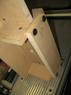
| Assembly of Z-top plate to vertical member |
 |
| Toggle close-up and slot tolerance |
 |
| Z-motor plate assembled to vertical member |
 |
| Carriage awaiting the Z-rail plate (under hammer-yet to be drilled) |
 |
| Z-rail plate getting holes drilled (has yet to have edges beveled) |
 |
| Z-rail plate installed |
 |
| Rear view of carriage |
 |
| Bottom of carriage showing precision fit of components |
 |
| Back support of carriage and drive-screw hole |
 |
| Side view of nearly completed carriage assembly |
Even though the carriage looks completed, I must yet bevel the edges to accept the Z-axis long rails on which the router will ride. Another item is the lower Z-axis drive screw support which will need to be attached the lower front of the rail plate.
 |
| Side view of the router support grips |


